
12-24 VDC - Synchronized 4 Channel Hall Effect Actuator Control - 25A - Wireless Remotes
Skip to product information
1 of 8

12-24 VDC - Synchronized 4 Channel Hall Effect Actuator Control - 25A - Wireless Remotes

12-24 VDC - Synchronized 4 Channel Hall Effect Actuator Control - 25A - Wireless Remotes

Model: PA-41-4-12V24V

Low stock
Ships within 24 hours
Volume Discount
1-6 units $525.00 CAD
7-9 units $509.25 CAD
10–19 units $498.75 CAD
20–49 units $488.25 CAD
Regular price $525.00 CAD
Regular price Sale price $525.00 CAD
Sale Sold out
  • Linear Actuator Calculator
  • Get Free Actuator Guide
View full details
Description
PA-41-4-12V24V Specifications

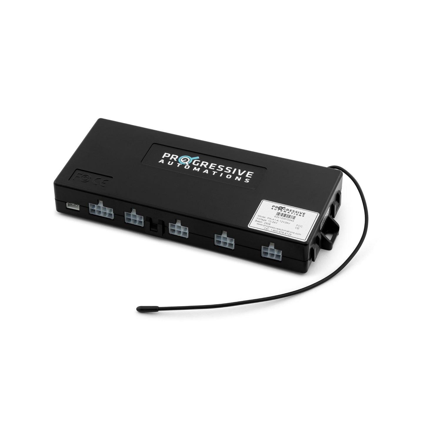
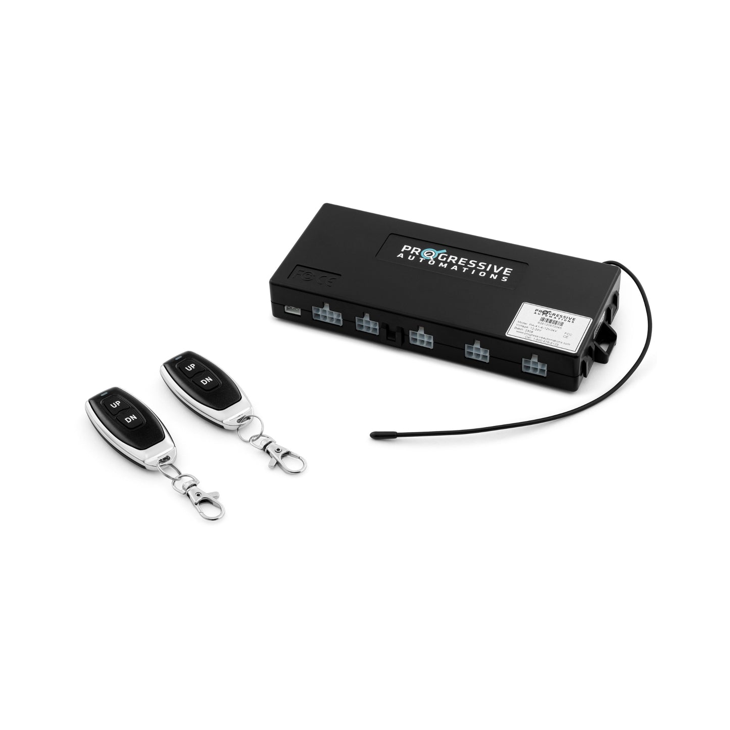
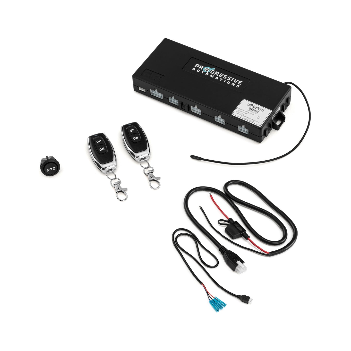
The PA-41-4-12V24 control box allows for synchronous control of four linear actuators with hall effect feedback. Using either of the 2 wireless remotes provided, users have the ability to extend, stop, and retract their synchronized actuators from up to 100 feet away (open air). The control box has both momentary and non-momentary capabilities for the wireless remotes, a wired RC-13 momentary rocker switch, as well as an in-line fuse to protect against short circuits.

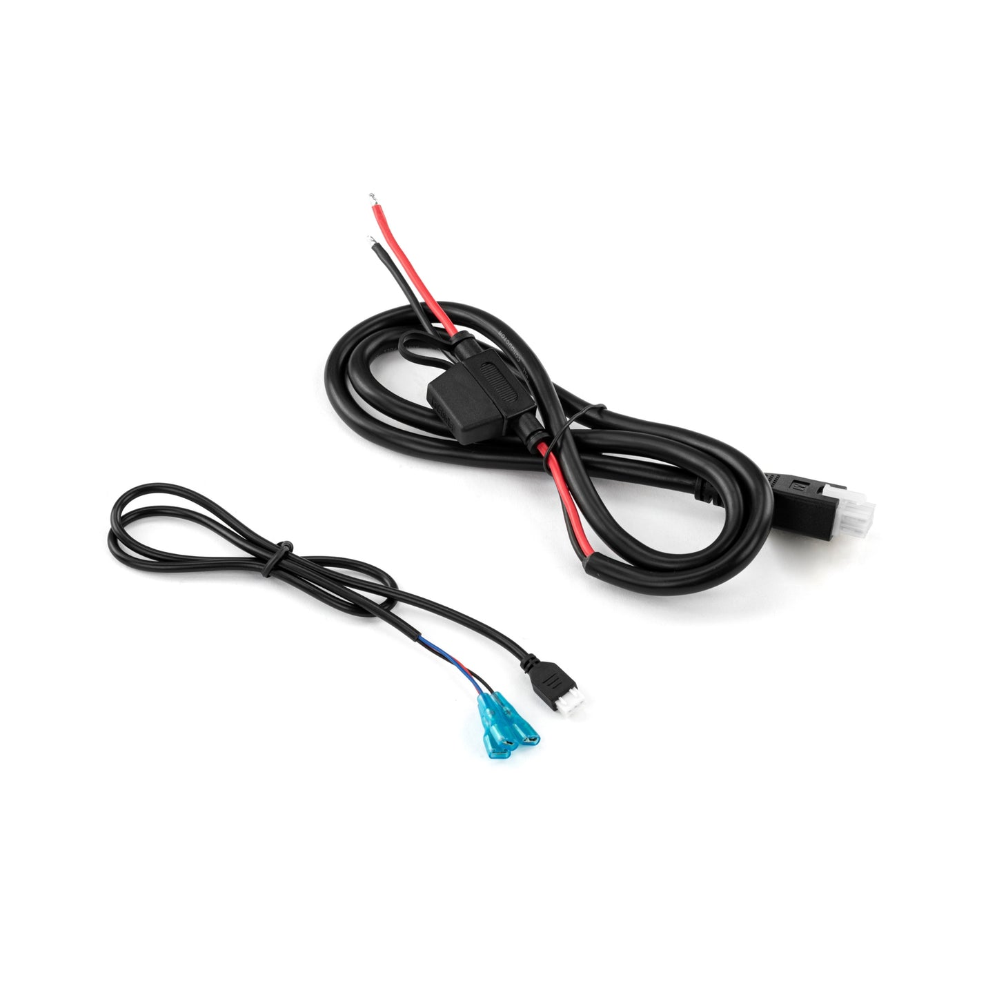
Using the included wire harness, connect the linear actuators to the control box. Apply 12-24 VDC across the power wires and the system is now ready to use. It is important to ensure that the power supply has a sufficient amperage rating to control the linear actuators. The PA-41-4-12V24 is designed to handle a maximum of 6.25 A per channel at 12 VDC and 5 A per channel at 24 VDC.

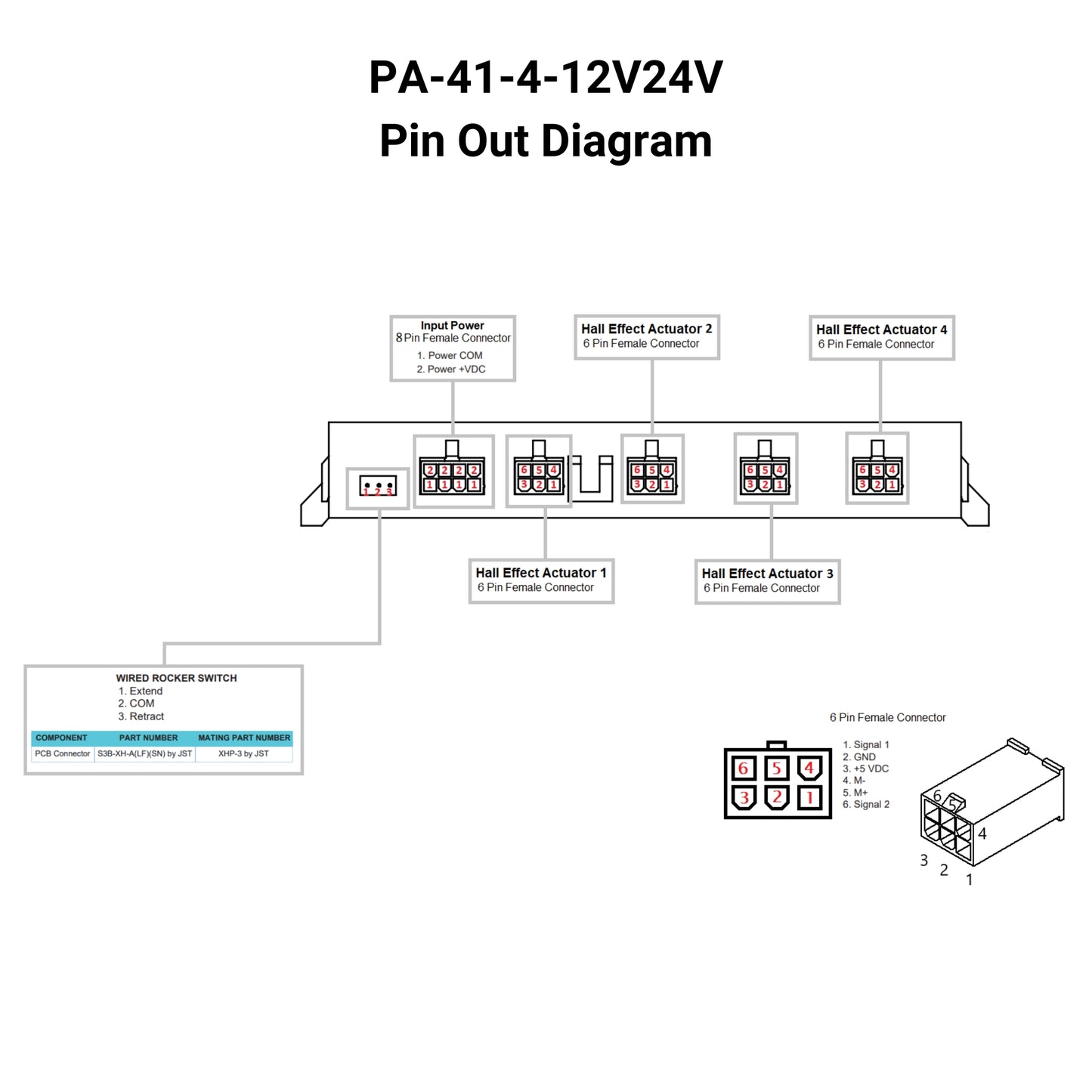
Please see the PA-41-4-12V24 Data Sheet for information about controls, wiring, and troubleshooting.

* Only compatible with 12 VDC or 24 VDC hall effect type actuators. Controls 4 matching Hall Effect actuators simultaneously to travel the same speed together in the same direction. Ensure PA-04-HS actuators are not fully loaded to stay within the current rating.

Overview
PA-41-4-12V24V Specifications

The PA-41-4-12V24 control box allows for synchronous control of four linear actuators with hall effect feedback. Using either of the 2 wireless remotes provided, users have the ability to extend, stop, and retract their synchronized actuators from up to 100 feet away (open air). The control box has both momentary and non-momentary capabilities for the wireless remotes, a wired RC-13 momentary rocker switch, as well as an in-line fuse to protect against short circuits.

Using the included wire harness, connect the linear actuators to the control box. Apply 12-24 VDC across the power wires and the system is now ready to use. It is important to ensure that the power supply has a sufficient amperage rating to control the linear actuators. The PA-41-4-12V24 is designed to handle a maximum of 6.25 A per channel at 12 VDC and 5 A per channel at 24 VDC.

Please see the PA-41-4-12V24 Data Sheet for information about controls, wiring, and troubleshooting.

* Only compatible with 12 VDC or 24 VDC hall effect type actuators. Controls 4 matching Hall Effect actuators simultaneously to travel the same speed together in the same direction. Ensure PA-04-HS actuators are not fully loaded to stay within the current rating.

Product Specifications
Number of Channels4
Input Voltage 12-24 VDC
Output Voltage 12-24 VDC
Max Current at 12VDC Per Channel 6.25 A
Max Current at 24VDC Per Channel 5 A
Duty Cycle 10% (2 min on, 18 min off)
Feedback Input Hall Effect Sensor
Operational Temperature -30°C to 60°C (-22°F to 149°F)
Housing Color Black
Housing Material Plastic
Certifications CE, FCC
Kit Includes 1 control box, 2 wireless remotes, 1 power wire harness w/ in-line 30A fuse, 1 Remote Sync Pushbutton, Wired Rocker Switch (RC-13)
Wireless Frequency 433.92 Mhz
Wireless Range 100 Ft
Wireless Remote Functions Up, Down, Pause (Momentary/Non Momentary Modes)
Wired RockerIncluded
Remote Battery Type 2x CR2016 3V Lithium cell
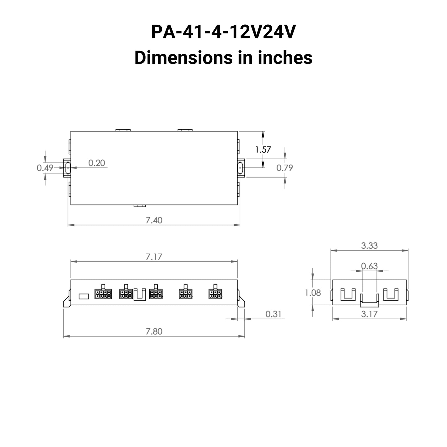
Dimensions 7.87" x 3.35" x 1.10"
Warranty18 Months
Control Boxes Compatibility
Technical Information

Following a set of standards is crucial for businesses to ensure their products and services can meet a level of quality that promotes customer satisfaction. At Progressive Automations, we aim for nothing but the best for our customers and strive toward continual improvements. Because of this, we are excited to announce that Progressive Automations is now ISO 9001:2015 certified!

Read More

Data Sheets

PA-41-4-12V24V Data Sheet

Data Sheet for PA-41-4-12V24V

View
Video & Articles
Videos
Related blog articles:
Photo of track linear actuators and text in the centre "Track Linear Actuators features and applications"

Track Linear Actuators and Their Further Applications

Nathan Bong

A track linear actuator’s operation is similar to a standard actuator except that its range of mo...

Learn more
Support
FAQ
How Can I Determine Which Progressive Automations Linear Actuator is Best Suited for My Application?

Depending on your application, there are different specification requirements you should consider when determining the linear actuator you need. These requirements include force, stroke, speed and mounting dimensions. For detailed actuator information, you can refer to either the datasheet or the specification table located on the selected actuator's product page. You can also contact us to speak with one of our expert engineers.

What Is Duty Cycle and How Is It Calculated?

Duty cycle is the fraction of the working period in which a linear actuator can remain active. You can calculate the duty cycle of a linear actuator by using the following equation: Duty cycle (%) = (Time the linear actuator is active) / (Time for one working period)

For example: With a 25% duty cycle, an actuator can run for 5 minutes continuously before needing to rest for 15 minutes before operating.

What Does Stroke Mean? How Am I Supposed to Know Which Size to Choose?

Stroke is the travel distance of the extending rod. To find the stroke length you require, measure your application from the fully retracted position to the fully extended position. The difference will equal the stroke length you require.

How Do I Know Which Force Rating Is Right for My Application?

We always recommend purchasing an actuator with a higher force rating than what the application requires. If unsure of your force requirements, this article may help you calculate this: How to Calculate Force to Find the Right Linear Actuator

Can I Synchronize My Linear Actuators?

Yes, this is possible. However, it does depend on the units you are currently using. To synchronize actuators, they require a form of feedback such as a potentiometer or hall effect sensors. For more information, see below some of our key content regarding linear actuator synchronization.

Controlling Multiple Linear Actuators at the Same Time

How To Utilize FLTCON-2 & FLTCON-4 Control Boxes?

What Are the Control Box Options For My Actuator?

The control box you choose should be able to provide sufficient voltage and current rating to your actuator. If you are unsure of the specifications, please contact us.

Alternatively, you can also find compatible control boxes on your selected linear actuator's product page.

What Is Backdriving? -- What Does Dynamic and Static Load Ratings Mean? -- What Is Lateral Loading?
What Is Backdriving?

Backdriving is when an actuator starts sliding down under load, when it is either overloaded or when the actuator has been damaged. Watch the video.

What Does Dynamic and Static Load Ratings Mean?

Dynamic load rating is the amount of weight an actuator can pull or push safely when being powered. Static load rating is the amount of weight the actuator can hold or withstand without back driving when it is not being powered. For example, let's just say you have an actuator installed on a window and the static load rating of the actuator is 100lbs, it could experience backdriving when there is a high wind event, which means there will be more pressure exerted on the actuator which would exceed the 100lbs load rating of the actuator.

What Is Lateral Loading?

Lateral loading is when the actuator experiences forces from the lateral plane. Actuators are not meant to handle lateral forces at all so if it experiences any lateral forces, it will likely damage the actuator or bend the rod. So it's advised never to use lateral forces and always make sure the actuator is fully in line or in sync with your application, so it does not take any load other than the axial load. Watch the video.

Recently Viewed