


Have you ever faced a situation where you must connect a lower voltage actuator with a higher voltage control unit, or wondered about the compatibility of a 24-volt relay for a 12-volt actuator? We offer the PA-VC1 for converting 12 VDC into 24 VDC, however, this device is unable to convert 24 VDC into 12 VDC. Most of our in-stock actuators are available with 12 VDC motors and would not be directly compatible with 24 VDC signals or power. Custom manufacturing is possible for most models to have 24 VDC motors; however, the lead times can range from 6 to 8 weeks. Another solution is to use 24 VDC relays to allow control while still isolating a 12 VDC actuator from the 24 VDC being supplied by the pre-existing 24 VDC control system.
In this blog, we will take you through how to use a 24-volt relay on a 12-volt system, and provide reference on how to use relays to allow a pre-existing 24 VDC control system to control 12 VDC actuators. Relays make use of an electromagnet that when energized would mechanically pull a switch to change contact points. A low current signal at 24 VDC can run through the coil inside the 24 VDC relay to switch between the normally open node (NO) and the normally closed node (NC), in which each node can be connected to a 12 VDC source to power a 12 VDC device or actuator.
Components Used
- 2 x AC-31-30-24 Single Pole Double Throw Relay (24VDC)

- 1 x PS-40-12 110-220VAC to 12VDC power supply with a current rating of 40A

- 1 x PS-20-24 110-230VAC to 24VDC power supply with a current rating of 20A

- 1 x AC-17 Wiring Kit

- 1 x PA-09 Mini Industrial Actuator (12 VDC actuator used for demonstration)

- 1 x RC-12 Momentary Rocker Switch (used to simulate 24 VDC control system)

Wiring Guide Reference
The first step is to make sure your 24 VDC pre-existing controller is receiving input power from the appropriate 24 VDC power source. For ensuring safe motor operation, we will then need to use the 24 VDC controller’s output current to drive our relays instead of directly powering the 12 VDC actuators. So first we need to connect each of the output pins from the controller to one of the input pins on both SPDT relays (figure 1).

Figure 1
Then, we will take the positive and negative output from the actuator and connect them to each of the output pins on the two SPDT relays (figure 2).

Figure 2
To complete the relay input circuit, we will need to connect the remaining input pins from both relays to the ground of your 24 VDC power source (figure 3).

Figure 3
All that remains is to connect the 12 VDC power source to relay, so it can drive the 12 VDC actuator. To do that, we will connect the negative terminal from the power supply to the Normally Close Node (NC), and the positive terminal of the power supply to the Normally Open Node (NO) for both relays (figure 4). Now the circuit is complete.

Operation
When no power is applied, both relay output is connected to the NC pins (0VDC), which is connected to the ground. Therefore, the actuator is receiving 0VDC from the relays, and it remains stationary.
When an extended command is issued to the controller, Relay A will receive 24VDC from the controller, and Relay B will receive 0VDC (figure 5).

Figure 5
This will cause Relay A output to switch to NO pin (12VDC), and Relay B output remain at NC (0VDC). At this point, the actuator will receive +12VDC from the output of the relays, and it will extend (figure 6).

Figure 6
When a retract command is issued to the controller, Relay A will receive 0VDC, and Relay B will receive 24VDC. This will cause Relay A output to remain at NC (0VDC), and Relay B output to switch to NO (12VDC). At this point, the actuator will receive -12VDC from the output of the relays, and it will retract (figure 7).
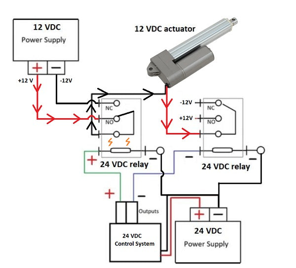
Figure 7
Since 24 VDC power is supplied from the controller through the relays, it will not go through the 12 VDC actuator directly; effectively bypassing the previous voltage incompatibility issue of the actuator.
How do you power a 12v linear actuator?
"12v" is better known as "12 VDC" and refers to when direct current is used to power actuators that have a DC motor. For a standard linear actuator, there will be two lead wires that extend from the motor; a positive wire (usually red) and a negative wire (usually black). By using a 12 VDC power supply (a car battery, for example), if you connect the + terminal to the red wire and - terminal to the black wire, the motor will rotate and the stroke rod will extend. If we reversed the polarity and applied - to the red wire and + to the black wire, voltage to the motor will have the motor spin in the opposite direction, making the stroke rod retract. This is the basic function of applying power to a 12 VDC linear actuator, but keep in mind that the amperage will have to be sufficient for the actuator's current draw. You must meet the threshold of the linear actuator's motor, but you typically can't use 'too much' amperage from the power source.
Conclusion
To summarize, many 12 VDC actuators can meet the specification requirements of an application while being readily available. Having a lower voltage operation can make the actuator tricky to safely integrate with a pre-existing higher voltage control system. If you need a 24-volt powered relay to complete a 12-volt circuit, with this instructional article and the right components, this problem can be solved with very little time and resources.
If you had any further questions, you may call us at 1-800-676-6123 or email us at sales@progressiveautomations.com, we’ll be happy to help!