


)

Some electric actuators have an in-line or tubular shaped design; however, many models have the motors protruding outwards from its side. Because of this, the mounting holes may need to be rotated depending on the mounting requirements of a project. This can sometimes be due to tight space requirement or a project’s framing being in the way of an actuator’s side motor housing. Please note that certain actuators may have slightly different procedures depending on if they were custom ordered or if they were a discontinued version. Our standard model actuators are the focus of this article and will give an idea on how to rotate some of the rotatable mounting holes of our actuators.
Although we can customize the majority of our products with the mounting holes rotated, the custom manufacturing lead times can range from 6-8 weeks and the custom manufacturing fees may vary. If you require standard actuators with mounting holes rotated sooner and can sacrifice the Ingress Protection after rotating the mounting holes, this article is for you!
Rotating Stroke Mounting Holes of Electric Linear Actuators
PA-12
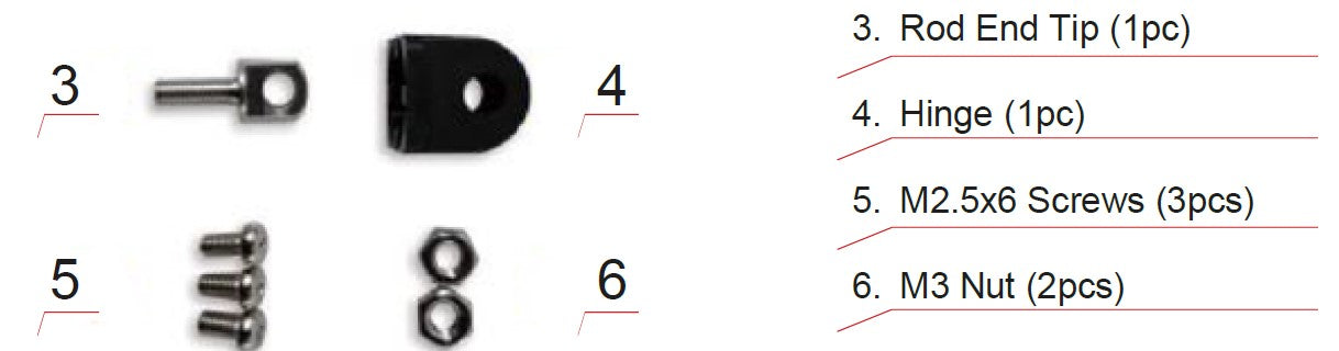
Rotation of the PA-12 mounting holes can be done just by bare hands to screw and clip the mounting pieces into place. Below we explain how to install the mounting ends and rotate the mounting holes of our PA-12 Micro Precision Servo Actuators:
Step 1:
Place the first M3 Nut into the rod end tip by rotating it clockwise until it reaches the bottom of the Rod End Tip.
Step 2:
Place the second M3 Nut into the rod end tip by rotating it clockwise until it reaches as far bottom as possibly can.
Step 3:
Screw the rod end tip clockwise into the front of the PA-12 until it reaches the farthest into the PA-12 it can.
Step 4:
Once the rod end tip reaches as far into the PA-12’s front as it can, you may rotate it slightly counter-clockwise to face the mounting hole position you required.
PA-14, PA-03, PA-04, PA-09 & PA-10
Our PA-14 Mini Linear Actuator’s front mounting hole can be rotated counter-clockwise 90° by placing a screwdriver into the mounting hole and then rotating the screwdriver to the 90-degree position. If this is the first-time rotating the mounting hole, some torque may be required. This procedure is the same for rotating the front mounting holes of our mini and standard sized actuators such as models PA-03, PA-04, PA-09 and PA-10 as seen in the GIF below:

Step 1:
Place a screwdriver into the stroke mounting hole.
Step 2:
Rotate the screwdriver counter-clockwise to the 90 degree position. If this is the first-time rotating the mounting hole, some extra torque may be required.
Step 3:
Remove the screwdriver and your stroke mounting hole rotation has been completed.
PA-17 and PA-13
Step 1:
Supply the appropriate voltage (see actuator’s sticker/label) to the actuator and extend stroke enough to place the stainless-steel shaft into a vice.
Step 2:
Using a piece of leather or something similar to protect the shaft from the vice plates, clamp the shaft with just enough pressure to prevent it from slipping during the following steps.
Note: Either end will require some torque to rotate.
Optional: Use a heat gun briefly to heat up the black mounting point to reduce torque required when rotating.
Step 3:
Clamp the stainless-steel shaft and rotate the front end's mounting point 90° counter-clockwise.
Step 4:
Do not rotate more than 90°.
Step 5:
Rotation complete.
Rotating Motor Mounting Holes of Electric Linear Actuators
PA-14 & PA-08
The base covers of the PA-08 are similar to PA-14 models and can follow the same procedure. To have the rear mounting holes rotated for either the PA-14 or PA-08, a separate base cover piece with the mounting hole rotated will be required. We offer the PRT-14-8B which has the mounting point rotated 90°.
Step 1:
Completely remove the three base cover screws and washers (below in the red circles) by rotating them counter-clockwise using a screwdriver.

Step 2:
Remove the old base cover by pulling it in the direction away from the rest of the actuator’s body.
Before: After:

Step 3:
Place the new replacement base cover into place and secure it with the three base cover screws and washers below in the red circles by rotating them clockwise using a screwdriver.
PA-04
Step 1:
Completely remove the four mounting bracket screws by rotating them counter-clockwise using a screwdriver.
Step 2:
Remove the case mounting bracket pulling it in the direction away from the rest of the actuator’s body.
Step 3:
Use a pair of pliers to rotate the internal torsion spring counter-clockwise 90°.

Step 4:
Insert the case mounting bracket back and ensure it has been rotated 90° counter-clockwise from its original position.
Step 5:
Secure the case mounting bracket firmly with the four mounting bracket screws by rotating the screws clockwise using a screwdriver.
PA-03
The rotation of our PA-03 rear mounting holes has some slight differences from the PA-04 since they do not have the same rear mounting piece.
Step 1:
Completely remove the four mounting plate screws by rotating them counter-clockwise using a screwdriver.
Step 2:
Remove the bottom cap mounting plate, pulling it in the direction away from the rest of the actuator’s body.
Step 3:
Remove the bottom cap with the mounting hole, pulling it in the direction away from the rest of the actuator’s body. Some extra force and effort may be required for this step, but it should be possible to remove by hand and a good grip.
Step 4:
Use a pair of pliers to rotate the internal torsion spring counter-clockwise 90°.

Step 5:
Insert the bottom cap with the mounting hole back and ensure it has been rotated 90° counter-clockwise from its original position.
Step 6:
Insert the bottom cap mounting plate back into its original position.
Step 7:
Secure the bottom cap mounting plate firmly with the four mounting plate screws by rotating the screws clockwise using a screwdriver.
PA-13
This PA-13 video illustrates how to rotate the mounting holes of a PA-13. An older model is being used as an example; however, the procedures are very similar for both new and older model actuators. The major difference is the visual appearance from the exterior of the newer and older model PA-13:

Our older PA-13 model has rounded edges for the motor housing.
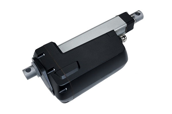
Our newer PA-13 model has squared edges for the motor housing.
Step 1:
Remove the large nut that holds the mounting component as well as the large screw.

Step 2:
Now, loosen all six screws located at the back of the mounting plate and then remove the back mounting plate.

Step 3:
Slowly remove the back casing to prevent damaging the gasket.
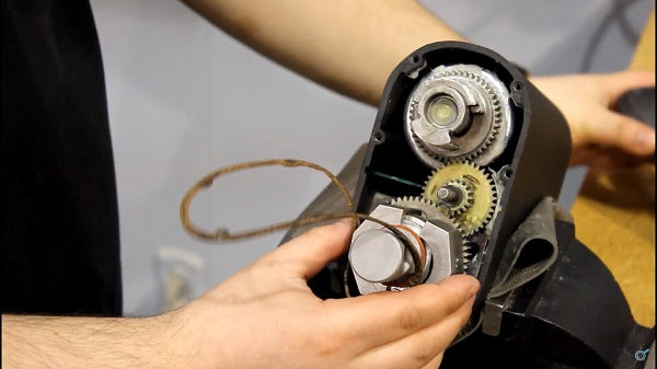
Step 4:
Remove the metal component that’s holding the mounting piece, then remove the mounting piece from the actuator.

Step 5:
Remove the spring with a pair of pliers. Make sure not to pull too hard and deform the spring.

Step 6:
Next, take out the spring, place the spring as shown.

Step 7:
Position the mounting piece at the angle that you like. Then place two halves of metal pieces back on to the mounting piece.

Step 8:
Put the gasket back on to its original place and then put the mounting plate on.
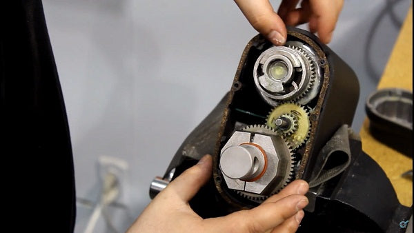
Step 9:
Add all the screws back in as well as the mounting nut.

PA-17
Step 1:
Loosen the large nut attached to the mounting point using a wrench or an Impact Driver with Power Nut Driver Bit.

Step 2:
Push in on the mount enough to disengage internal locking teeth and rotate 90°.

Step 3:
Retighten the large nut and torque to a similar pressure that was needed to first loosen.
Step 4:
Rotation complete.
Conclusion
To summarize, many actuators may need their mounting holes rotated for certain installation conditions and space requirement. By using a few tools and spending some time to follow our step-by-step guides, you too can rotate the mounting holes of an actuator to the required positions.
If you required further assistance or had more questions on how to rotate actuator mounting holes, you may call us at 1-800-676-6123 or email us at sales@progressiveautomations.com.