


Outdoor camping is a fun and exciting activity that many of us enjoy, however, space constraints can make the process of bringing all our favorite luxuries quite challenging. This is where innovation and creativity can help us in building a comfortable yet space-efficient camping environment. If you were thinking of making projects similar to an RV dinette table or an RV bed lift system, this article is just for you! We will be covering how Chad from Broke OverLand made a Bed Lift System and Dinette Table for his LMTV camper!
Bed Lift System
Chad’s latest bed lift project uses four track actuators to replace his previous Bed Lift System which did not have a sufficient stroke length. He also found that his previous system would not have been able to meet the space requirements inside his LMTV camper even if the design was modified to have sufficient stroke length. For this reason, Chad ordered our PA-18 track actuators which were customized for:
- 38-inch stroke
- 225 lbs force rating
- Hall effect sensor feedback
- 24 VDC motors
Since track actuators do not have a shaft that protrudes outwards, they have the advantage of being compact while fully extended. Hall effect sensor feedback was to allow for synchronous motion of the four actuators later in the build.
Check out the build video of Chad’s Bed Lift System:
Chad begins his project by building some brackets for the track actuators so that they can mount to the 80/20 aluminum frame on the bottom of his LMTV camper. Since the original bottom brackets of our PA-18 actuators were meant for wall mounts, Chad will be replacing them with the custom brackets he made later in the project. These will be custom brackets that are suitable for mounting to his 80/20 aluminum frame.

Choosing a chunk of angle aluminum that is roughly the same thickness and depth as the original bracket piece gives Chad the required offset to hold his actuators away from the wall so that its track can cycle. He then proceeds to cut a wider chunk of aluminum, taps the required holes, and drills through the tapped holes. Once completing the prototype bottom bracket, Chad secures them to a PA-18 actuator and installs mounting screws so that they will lock into the 80/20 aluminum frame.

Chad then proceeds with the making of his upper brackets. An aluminum rod is milled down to the size that will go through the upper bracket. Unlike a bolt system, this project will enable for a pin system to make the installation possible in the given space constraints of the LMTV camper which does not have enough room above the setup to fit a wrench.

After successfully making the prototype mounting bracket, Chad proceeds with making the bottom brackets with thicker material. Doing so allows for Chad to make a slight recess to countersink the heads of his screws so they will be flush against 80/20 aluminum frame and still have room for his bolts.

By using the same tools and a similar build process, Chad cuts his upper brackets into shape for the actuators to mount in the ceiling. He also made some pins that he can place through the upper brackets with cotter pin inserts. This pin system will make installation with needle nose pliers possible later in the build.

Chad places his mounting brackets and actuators against the walls of the LMTV camper to determine where he will need to drill pilot holes. He then drills pilot holes into the 2x2 steel at the top of his truck and uses a 90-degree bit with self-tapping screws to bite into these pilot holes.

Once all his mounting brackets are secured using the self-tapping screws, Chad proceeds with mounting the four PA-18 custom actuators to the brackets. He had previously cut a spacer hole at the top to get access to the 2x2 steel up in the ceiling for mounting the upper portion of his track actuators. Each actuator is mounted with one pin at the top and two bolts at the bottom.

Chad cuts the wires of his PA-18 actuators to shorten their length and later adds his own Molex connectors to the wire ends. This is to make the process of swapping the PA-18 actuators easier in case a unit were to become faulty and require future replacement. Chad then wires the four actuators to our FLTCON-4 control box and RT-11 remote which keeps the actuators moving at the same speed together. Since the actuators were customized with 24VDC motors, they were compatible with the FLTCON-4 control box.

Bed Frame
After the completion of his Bed Lift System, Chad proceeds with designing and making his bed frame. Our FLTCON-4 control box is only able to control all four actuators to move together at the same time, however, Chad may modify his project in the future so that each actuator can move individually as well. While keeping this plan in mind, he designs his bed platform with custom brackets and Heim joints that could also allow the option to articulate in the X and Y axis in his future project.
Watch how Chad makes his LMTV camper bed frame:
Welding coupons were used to stamp out the brackets that go on the track pieces of the four track actuators. Chad uses our PA-18 datasheet as a reference during the making of his bed frame mounting brackets. A 1-inch bar stock was later milled down to the required dimensions for his pins. For the best accuracy possible, Chad uses a digital caliper to measure the diameter of his pin each time he pauses between the milling process.

After adding cutting lube, Chad proceeds to cutting out the inner treads for his pin. A vice is used to secure the pin as he manually makes the treads. A 14-millimeter thread pattern was used so that it will match the back of his Heim joints. He also uses a knurling tool to make a pattern around his custom pin so that it has better grip.

If Chad changes control systems in the future, he can swap the custom pin for a longer rod and then put springs between his Heim joints and brackets. The springs would be to allow for the bed platform to slide and tilt slightly while still providing some tension to assist in centering the bed platform.

Aluminum channels were then used as the sides of the bed rails which were later attached to the mounting brackets of the bed frame. Planks of tongue and groove cedar were pre-stained and cut into shape. Each plank was then numbered in the order that they will be placed onto the bed platform. This allows the bed frame to have an appearance which matches the screw patterns of the LMTV camper’s roof.

Chad then measures out the bed platform and carefully determine where he will place his light fixtures. These light fixtures are going to be for the Dinette Table below the Bed Lift System. After confirming where he will place his lights, Chad drills four holes below the bed platform and mounts his lighting fixtures.

Plywood was later placed on the top of the bed frame to support the weight of his mattress. To keep the electrical wiring of the light fixtures tidy, a weight or a spring can be used to pull the cable down into the LMTV camper’s cabinet when the bed raises up. As the bed lowers down, the cable will be fed out from the weight of the bed.

Dinette Table
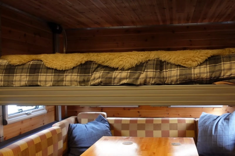
The final part of this build is a Dinette Table which goes underneath the Bed Lift System. Installing a Bed Lift System on top of an adjustable Dinette Table allows for maximum space efficiency without compromising the usability or comfort of each project. By raising the Bed Lift System, users have all the height they need when using the Dinette Table. Lowering the Bed Lift System allows for a comfortable sleeping height when the Dinette Table is no longer in use.
For the full Dinette Table build video, please check out the video below:
Chad uses his old 3/8-inch tabletop as the reference pattern for his new tabletop build. A Baltic Birch style butcher block counter is used as the new material tabletop material. Chad begins this build by cutting the rough shapes he needs using an electric skill saw.

A jigsaw is typically recommended for making curved cuts; however, Chad had a limited selection of tools in this case and had to make multiple straight cuts with his skill saw to get a curved cut. Once he has the two curved corners of the tabletop, he uses an angle grinder to grind down the edges of his cuts.

Once his tabletop has been shaped, he proceeds with staining the tabletop and later adds three or four coats of Butcher Block countertop sealant.

The tabletop is then placed on to our FLT-11 lifting column for the next step. Chad carefully measures out the location where he will mount his tabletop onto the lifting column.

After confirming the tabletop placement, Chad goes underneath the FLT-11 lifting column to drill into the tabletop. He secures the tabletop and lifting column together using stainless steel screws.

Now we have introduced our modular lifting columns, 1x LG-11 lifting columns, 1x FLTCON-1 control box, and 1x RT-11 remote works just the same as the FLT-11! Our modular lifting columns are single-unit legs of a lifting column that can be paired with our remotes and FLTCON series of control boxes that can handle between 1 to 4 legs in a single control system. Select from our large range of remote options and enjoy all the unique features of our different programmable wired remotes that can be used together with wireless remotes for extra convenience. Chad finally places his cushions around the seated area to complete the Dinette table build.

Due to miscalculations, the back cushion was not able to fit in the space of the tabletop. This means that the lowered Dinette Tabletop will not be able to convert into a 2nd bed, however, it still fully functions as an adjustable Dinette Table.

The control boxes of his Bed Lift System and Dinette Table are both mounted with screws to the wall at the back of the Dinette area. These control boxes are connected to the AC power supply of the LMTV camper. For added safety, a plywood cover is used to keep the wiring away from the seats and cushions. The controllers for both the Bed Lift System and table lift are located next to the Dinette Table for convenient access.

If you were curious to know more about the Bed lift System or Dinette Table, please see the video below!
Answering Table and Bed lift questions, in the LMTV:
IN SUMMARY
By following the build process and using the right supplies, Chad now has his very own Bed Lift System and Dinette Table for the LMTV camper. For more cool projects by Chad from Broke OverLand, feel free to visit his Youtube channel!
Thank you to Chad for sharing your project - We are delighted to see you enjoying your new LMTV camper setup!
If you have any custom projects, applications, or technical questions about our products, feel free to reach out to us anytime. We are experts in what we do and will be happy to assist you with your future custom projects!
sales@progressiveautomations.com | 1-800-676-6123