


The PA-12 electric linear actuator is a fantastic example of lean design principles and represents the future of linear motion. If you are looking for a device that can deliver best-in-class performance in a compact package, look no further. The PA-12 is packed with modern solutions to recurring problems, and this article will provide a look into the main features of this actuator’s design. This linear actuator is purpose-built to provide the most precise movement possible at a high resolution, without requiring the user to determine control parameters or to compensate position readings for different load conditions. To do this, the actuator has a very high precision potentiometer with a built-in filter to reduce the electrical noise, and a very light motor to reduce the impact of inertia. We also sell PA-12 actuators with coreless motors, which can provide a significantly better performance than cored motors, and further contributes to increased accuracy.
This electric actuator come equipped with an on-board computer that will handle all the necessary calculations. It just requires the user to supply the commands in either TTL or RS-485 format. Alternatively, PA-12 can be connected to LC-12 computer controller, and you will be able to send commands through an interface on your PC. With all of that in mind, lets dive into the PA-12 and all it has to offer!
Movement Precision
We had an independent test performed on our PA-12 actuators to calculate its movement precision. The test was to accurately execute two servo counts per movement command, which would amount to 0.001074” per move. Measurements were gathered using a precision laser position indicator and the actuator also had a 15 lbs load attached to it for both extension and retraction. The results can be seen in the graphs below.
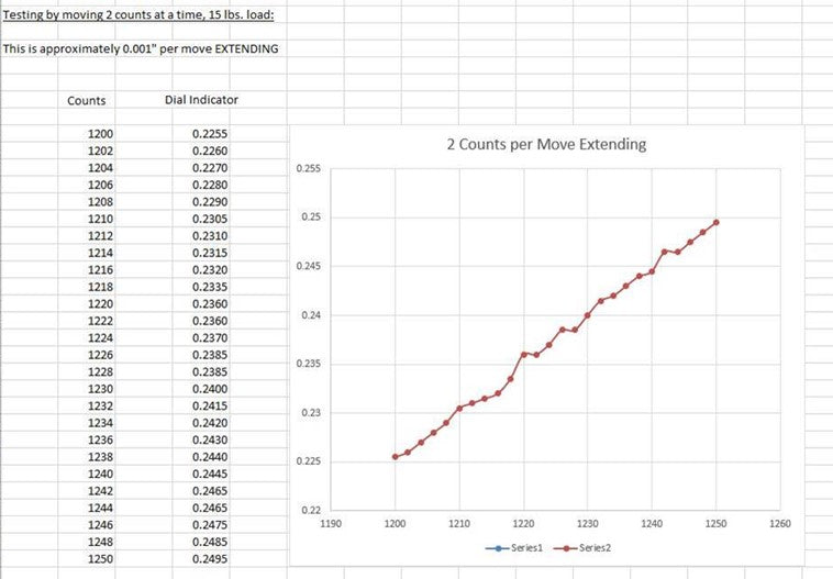

Most common instruments cannot accurately perceive a change in position that small. If the actuator were moving in larger increments, the results would have been even more precise. This movement is based on two factors – high precision from the built-in potentiometer and a properly calibrated PID controller. The parameters for PID control can optionally be changed through the digital commands but it is not recommended.
Cored vs Coreless Motor
PA-12 can come equipped with either a cored or a coreless DC motor. We will take you through the advantages and disadvantages of both.
Cored Motor
In a typical DC motor, a coil is wound around the iron core of the rotor. When a current is applied to the coil, it creates a magnetic field that, together with a stator, causes the rotation of the motor. The iron core brushed DC motor is a tested, reliable, low cost option. A cored, brushed DC motor would be able to run from straight-line DC voltage and handle high torque because of the iron core keeping everything rigid. The core also helps the motor achieve higher current draws because it acts as a heat sink and allows the heat to dissipate. This type of motor is very simple and yet effective, but it does have a few disadvantages.
A cored brushed DC motor tends to have lower acceleration and deceleration due to the added weight from the iron core. This motor also tends to have higher inductance, which means that there are more accidental electrical arcs between the commutator and the brushes. This effect would increase the wear on the brushes over time.
Coreless Motor
A coreless brushed DC motor is the solution to many of these problems. A coreless motor is constructed using a self-supporting winding mesh that does not need the core to keep it in the right shape. This makes the rotor very light, which means it can accelerate and stop much faster. It is more efficient, requiring less current to accomplish the same torque as the iron core motor. These types of sophisticated windings also have lower inductance, which means that the arcing between commutator and the brushes happens at a lower power and reduced frequency.
The disadvantages of coreless motors are the limited size, increased cost and the requirement for a heat sink. In a cored motor – the core takes care of moving the heat away from the coils, but you would need alternative heat management methods to make the coreless DC motor work consistently over a long time.
The PA-12 cored motor is already a very light construction with a compact size and reduced inertial load. For dedicated micro-positioning needs, it is probably a good idea to go with the coreless motor option as it will allow your application to achieve the best results.
Filtering and Noise
PA-12’s defining feature is the ability to make positional measurements using the potentiometer accurately and consistently. In order to accomplish this, the PA-12 comes with an analog-to-digital converter (ADC) meant to interface with the potentiometer. The on-board controller performs the filtering function for the signals coming from the potentiometer, converting the analog data into digital responses that can be sent through TTL or RS-485 communication packages. To make the readings possible under normal circumstances, the recommended data reading frequency is 100 times per second. This means that the position information can be updated at a rate of 100 Hz.
That being said, the PA-12 actuators are capable of a maximum data reading frequency of 500 times per second. The units would have to be custom configured at the factory to achieve this result, but it is possible to get high refresh rate without sacrificing accuracy.
Communication
The most important thing to keep in mind for these actuators is that they can’t be controlled through regular means. In order to achieve the performance, stability and positional accuracy of PA-12 actuators, the user is required to interface with the internal microcontroller through RS-485 or TTL protocol. For TTL-enabled units it is possible to communicate via servo pulses.
Both TTL and RS-485 represent standards in serial communications. They provide a framework to develop a set of commands and responses in 8-bit format that could be used to interface with the on-board microcontroller in PA-12.
The communication parameters for serial data connection for both TTL and RS-485 are shown below:

Structure
The data structure for communication with the PA-12 on-board microcontroller is half-duplex UART. A full-duplex communication system allows both devices to transmit and receive data simultaneously. In the case of PA-12, the system is half-duplex, also known as semi-duplex. This means that the devices can communicate to each other, but not simultaneously. At any time during communication, one device must transmit while the other one receives, and vice-versa.
For this reason, if you are trying to communicate with a PA-12 through a full duplex serial com device, you will need to use a buffer in between.

Figure 1: TTL/PWM communication wiring diagram for half-duplex
For TTL/PWM communication between a full duplex device and PA-12, we recommend implementing a 74LVC2G241 chip to act as a buffer. A full-duplex device can be something like an Arduino microcontroller. For detailed information on how to set this up, you can take a look at our article on getting started with Arduino and PA-12.

Figure 2: RS-485 communication wiring diagram for half-duplex
For RS-485 type actuators, we recommend using MAX485 chip as a buffer between a full duplex controller and the half-duplex PA-12 device. Of course, communication devices that are themselves half-duplex would have no problem communicating with PA-12 directly. For example, Allen-Bradley 1769-ASCII PLC module can communicate with the PA-12 directly.
Baud Rate
Baud rate represents the speed of communication between devices over the data channel. The default baud rate of PA-12 actuators is set to 57600 bps. If your communication device uses a different baud rate, then there are two ways of changing it. The easiest way is to connect the PA-12 to a PC through our LC-12 interface controller and make the changes through the app. Alternatively you can also set the baud rate through the RS-485 write command. This will require you to do the following:
1. Set the baud rate for the communication module to 57600.
2. Write the desired baud rate in memory address 0x04.

3. The value for the baud rate in address 0x04 must be set to one of 4 specific values, with 32 corresponding to 57600 being the default.

4. The PA-12 must be rebooted for these changes to take effect. You will have to turn the PA-12 off, then change the baud rate on your communication device and turn the system back on.
LC-12 PC Interface Controller
The easiest way to communicate with the PA-12 internal computer is through the LC-12 PC interface controller. It can be used to connect to both TTL/PWM and RS-485 actuators. The LC-12 is also required to download and install firmware upgrades.
The interface controller can be used to conveniently set operation parameters for the PA-12 actuators. For examples, in particular applications you may want to set extension and retraction limits, baud rate, maximum temperature, maximum current, maximum allowable position error, and so on. In large quantities, Progressive Automations will pre-program all the units but if you are dealing with production quantities of 50 or less, it may be easier to set the parameters through the interface.

LC-12 can be used to test the motion of the actuator without having to get bogged down trying to set up the TTL and RS-485 communication. The LC-12 will always be able to connect to the PA-12 actuator if there are no hardware issues. This could be useful when monitoring the parameters set in the memory data map to make sure nothing is out of place and fix the errors if necessary.
The PA-12’s internal computer will be able to self-diagnose issues and display error codes during operation. It may be difficult to tell exactly what is wrong with the actuator when simply receiving the feedback signals. The LC-12 PC interface would be able to search and display the errors that the actuator generates and make it easier to tell how to fix the issues. For example, if the actuator is not reaching the goal position, you can take a look at the error display and the current monitor on the interface and determine that there is an obstruction in the way.

Finally, the LC-12 PC interface controller has two important functions for the PA-12 actuators that make it an essential companion for initial sampling and troubleshooting. The LC-12 is the only way to reset the actuator back to default factory settings and to apply firmware updates.
Final Word
In this article, we have taken you through the key features of precision movement, cored vs coreless motors and the low noise of our PA-12 electric linear actuator. There are different ways to communicate with this actuator, with the LC-12 PC interface controller deemed the easiest by our engineers.
We hope you enjoyed this article – if you have any further queries about our PA-12 or any of the topics in this article, email us or else call on 1-800-676-6123 (toll free).