


The PA-18 Track Linear Actuator is our largest fixed-length actuator and is commonly used in custom cabinetry, home automation, and robotics. You can easily control an actuator with an Arduino board, and this article will showcase how to build and program an Arduino controlled linear actuator that can be easily adapted to fit your application!
Required Hardware
The following pieces of hardware are required for an Arduino controlled linear actuator, all of which can be purchased from Progressive Automations:
- 1x PA-18 Track Linear Actuator
- 1x Arduino Uno
- 1x MegaMoto Plus H-bridge
- 1x 12VDC power supply
- 2x Momentary pushbuttons
- Jumper wires
System Wiring
The actuator used in this setup requires a 12VDC input voltage and up to 8A of current at full load. These values are much higher than what an Arduino microcontroller is capable of supplying and will cause ‘magic’ smoke to come out of the Arduino. To avoid damaging the Arduino, the MegaMoto Plus H-bridge is used. The H-bridge can handle the power requirements and can easily be used to control an actuator with an Arduino.
For this system, there are connections from the Arduino to the MegaMoto Plus H-bridge, and to the two pushbuttons. Each pushbutton requires a single input, which are chosen from the Arduino’s available GPIO pins. The H-bridge has four connections to the Arduino, three outputs and one input. The pins used by the H-bridge are preset and cannot be changed.
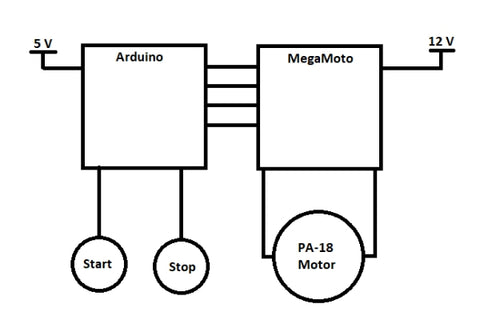
Block Diagram
The block diagram below briefly explains the power requirements and connections. The Arduino runs on a 5V supply and the H-Bridge runs on 12V. If you are using two separate power supplies, it is important that their grounds are shared to avoid a floating ground scenario.
Arduino Commands
You will need to install the Arduino IDE on a desktop computer or laptop. Bear in mind that your system wiring will affect your Arduino code. Therefore, it is important to double check your connections and compare it to the code you have entered.
The pinMode Arduino command is used to define the pins as inputs or outputs. To change what signal the Arduino is sending to a specific pin the digitalWrite and analogWrite commands are used. Additionally, the digitalRead and analogRead commands are used when the Arduino needs to check the signal on a specific pin.
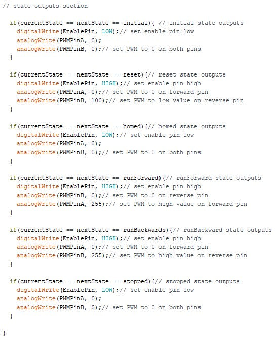
In the program below, the digitalWrite command is used to enable or disable the H-bridge, and to configure the pins used for the pushbuttons. The analogWrite command is used to set the value for the PWM signal in the range of 0 to 255 to the H-bridge. The digitalRead command is used to check if the pushbuttons have been pressed or released. The analogRead command is used to measure the current draw by the actuator motor, which will verify when the actuator is at the end of its stroke.
Arduino Code
The following section walks through the program definitions, setup, main loop, and pushbutton functions for an Arduino controlled linear actuator. It is important to walk through the code one line at a time to understand how it functions. This understanding will allow you to make adjustments based on your application.
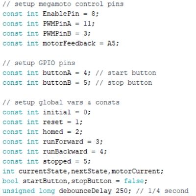
Program Definitions
This section of code is the pin connection setup. Double check that your connections to the Arduino board correlate with the numbers entered. These values can be changed based on whether you are attaching additional components to the Arduino that may then require shifting pin connections around.
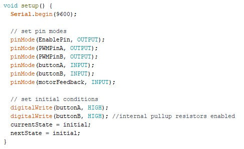
Program Setup
This section of code configures the connected pins as an input or output. The two buttons can be set to HIGH or LOW depending on how you have connected them (pull-up or pull-down). Although the Arduino has internal pullup resistors, you may want to add an external resistor to debounce the switches and prevent false firing.
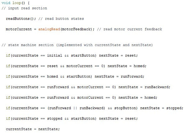
Main Loop
The main loop constantly checks to see the buttons have been pressed and runs a particular section of code depending on the result from the pushbutton function. A state machine section is included to determine what the Arduino controlled linear actuator is doing and how it should react based on the inputs (i.e., the pushbuttons).
Pushbutton Functions
These functions digitally read the state of the pushbuttons to control an actuator using an Arduino. Each pushbutton function has a debouncing loop within the main if statement to prevent misfiring and sending the wrong signal to the Arduino. A Boolean value is the output of these functions. For example, if the start button is pushed, the value of startButton will change to true. The Boolean value is then used in the main loop to make further decisions.

Final Words
The functionality of this system goes beyond what is showcased in this article. The Arduino microcontroller and MegaMoto Plus H-bridge can be used to implement much more complicated control routines. This setup is capable of variable speed control utilizing the analogWrite command to set the PWM signal. The actuator motor current could be monitored to be used for load sensing to trigger additional commands.
Moreover, additional sensors can be attached for an advanced Arduino controlled linear actuator. For example, an ultrasonic sensor can be attached to start/stop the motor when you are a certain distance away or it can be used to trigger a host of other exciting functionalities. The possibilities are endless. However, if pins are running low on the Arduino, you can opt for a different Arduino model. Alternatively, multiple Arduino’s can be daisy-chained together to talk to one another and various components. However, this route will involve a decent amount of programming experience.
For additional information, please send us an email at sales@progressiveautomations.com, or give us a call at 1-800-676-6123.