


A linear actuator is a common electro-mechanical component used in many applications. The unit is highly customizable and can be modified to fit into different environments and meet various functional demands. There are many sensors available to utilize linear actuators positional feedback feature. In this article, we will discuss how a linear actuator with a limit switch works and linear actuator limit switch wiring to fully understand feedback control.
Limit Switches in an Actuator
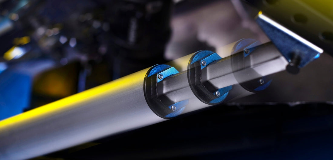
How does a limit switch work and what is the function of a limit switch inside a linear actuator? A mechanical limit switch is a component that is responsible for ensuring the device does not extend nor retract outside its mechanical dimension. An electric linear actuator moves as its motor spins, which drives the acme screw to push the shaft rod out or pull it in. The direction of the motor spin determines the direction of the shaft rod movement. However, without a mechanical limit switch, there are no stop points on neither end of the travel. The motor will only stop when the user manually turns off the power to the unit. This could cause a safety concern if the actuator travels to its mechanical limitation, but the motor is still running. The motor will stall when it can no longer rotate, causing a high current draw, and eventually burning out the motor.
To prevent this, a set of mechanical limit switches (or hall effect sensors) are installed in all Progressive Automations actuators. A linear actuator with a limit switch implements a mechanical trigger at either end of the travel, and the trigger causes the motor to shut off at the end of its travel. The circuit below is how our linear actuators are connected to limit switches.

Limit Switch Feedback in Linear Actuators
Some users’ application needs the limit switch feedback signals to control their system. Instead of using the mechanical trigger to shut off the motor, the application prefers to have an analog signal as part of an integrated control system. Currently, Progressive Automations offer two different configurations when it comes to limit switch feedback.
Option 1:
The ‘Common’ for both signals are separated. The extended limit switch and the retracted limit switch will provide an individual signal of normally open and closed to the users. The control system then can take that signal to monitor the positions and drive the motor to stop at the fully extended and retracted position.

Option 2:
Very similar to option 1, except now the extended and retracted mechanical limit switch share a common signal. This will still provide the same open and closed state, but with one less wire involved.
Both configurations can provide the signal needed to turn on or off the indicator light and notify the user that the unit has reached its final position. This is a common application for assembly line machinery, where the operator is usually away from the actuator, and they rely on the control panel indicators to alert them on the state of the operation. This can also be used as redundancy in a control loop to provide extra safety assurance to the user.
Final Word
The feedback from a limit switch in an actuator can help the user be more informed of the state of their application. This is just one of many ways a linear actuator can provide additional information needed to improve the functionality of a system. For further information and other feedback options, please visit our website or contact us at sales@progressiveautomations.com.